Aetec logo
AETECPIPE AUTOMATION
Q64 TTLOption 1 / Option 2 · Factory comparison
Complete lineSame recipe · same position under the overhead crane
CRANE BAY Rear ground floor · wall AOuter equipment → wall 660 mmMini warehouse → wall 1,460 mm
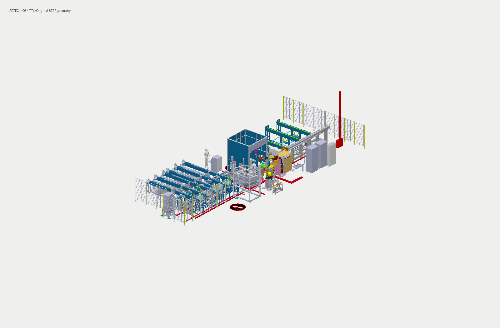
OPTION 1Original STEP assembly

Grooving retained · original conveyors

Loading original machine…
0 pipes
19.078 × 8.148 m equipment envelope
OPTION 2Compact layout

No grooving · shorter incoming transfer

Preparing modified assembly…
0 pipes
17.078 × 8.148 m · 2,000 mm shorter
Loading the two-option comparisonPreparing CAD geometry…
READYReady to runContinuous production starts when the machine is ready.

AETEC© 2026 Aetec Pte Ltd
Loading machine…Drag to orbit · pinch / scroll to zoom · right-drag to panOutgoing conveyor readySelect a machine component
Calculating batch comparison…Footprint reduced by 16.30 m² · timings are simulation assumptions
00:00 / 00:00
0Total pipes completed
0 / 4Sockets welded
Ø114.3 × 6,000Current pipe · mm
Assumed batch time
Robot clearance check pendingModel checks include nearby fixed parts. See Model details for limits.

Socket dimensions & orientation

Measure every socket centre from the First End cut face. Distances are absolute: for example, socket #1 at 500 mm and socket #2 at 4,000 mm.

Socket #1 sets the clock reference. For later sockets, leave the angle blank for the same orientation, or enter an offset such as 45°. Looking from First End: 0° up; positive angles turn clockwise. Sockets are radial to the pipe.

Close this editor, then Run this batch. Cutting happens underneath; the pipe rotates to present the opening upward for welding.

Source process video

Q64 model & motion

The machine geometry comes from your supplied Q64 TTL Pipe Robotic Welding Line.STEP. The original assembly can be viewed with Compare CAD assembly poses.

Updated 11 September 2026: side-by-side original and compact alternatives are placed at the same position under the factory crane. Option 2 omits both groovers, removes one incoming chain station, shortens two transfer members by 1,000 mm and relocates front guards. Its equipment envelope is 2,000 mm shorter. The original robot cell and outgoing conveyor are retained.

Factory wall gaps are measured from the drawing-based model. The mini warehouse is 1,460 mm from the wall; the outermost equipment has 660 mm. Upper floors are cut away for visibility. Conveyor edits are a layout proposal; final support, chain routing and fabrication details need engineering confirmation.

Process sequence: underside cutting, coordinated robot access and indexed outgoing movement follow your latest process instructions. Travel, joint motion and cycle times are demonstration settings; STEP does not contain the robot controller program.

Sample pipe dimensions demonstrate the sequence. They do not establish the machine’s approved capacity.